Wi-Fi RF Attenuator Kit
Overview
The NTA3000 hardware platform is QA Cafe’s most advanced network test appliance, providing significant upgrades over previous systems. In addition to the system itself, QA Cafe also offers the Wi-Fi RF Attenuator Kit (RAK). The RAK further improves the Wi-Fi testing experience and consists of the following elements:
- (1) Adaura AD-USB8AR48G120 8-Channel RF Attenuator
- (8) 240 series coax cables (2 foot)
- (3) RP-SMA plug terminators
- (1) USB cable
- (1) Ethernet cable
- (1) USB Drive (drivers, manual, etc.)
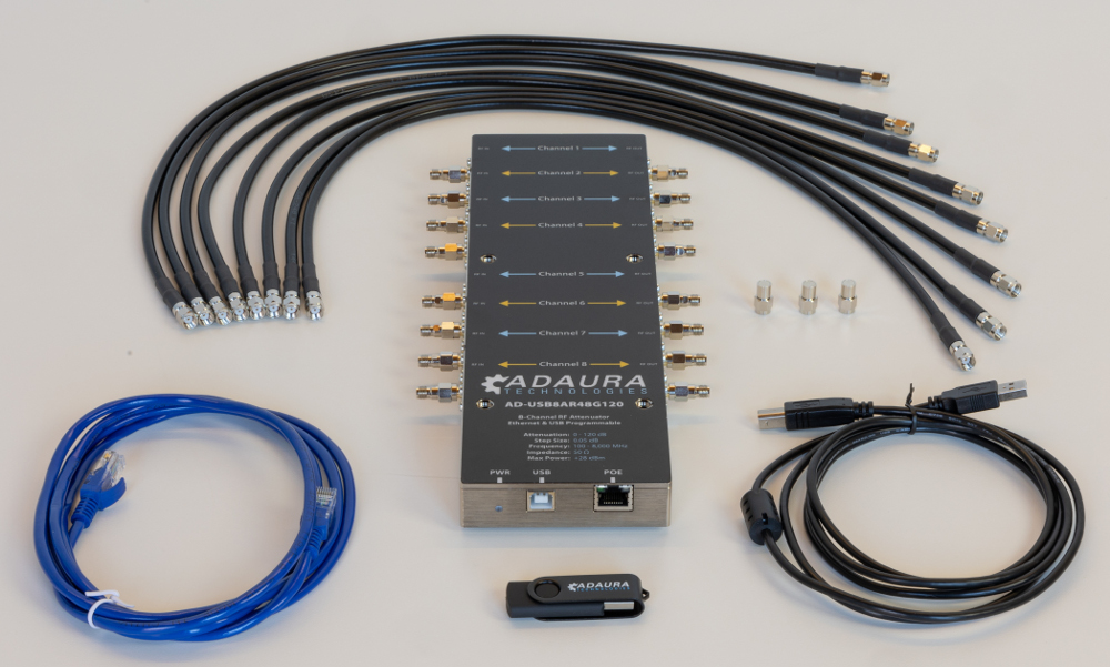
For pricing and other information, please contact sales@qacafe.com.
Adaura 8-Channel RF Attenuator
The Adaura AD-USB8AR48G120 8-Channel RF Attenuator is a hardware device that allows eight RF signals to pass through on eight individual RF channels. The device can introduce attenuation to the RF signal passing through each channel. The channels operate independently but can also be grouped and controlled together.
Key specifications:
- Attenuation Range: 0 - 120 dB
- Attenuation Step Size: 0.05 dB
- Operating Frequency: 100 - 8000 MHz
- Impedance: 50 ohm
- Max Input RF Power: +28 dBm
- Switching Speed: 550 usec
Setup
The Adaura 8-Channel RF Attenuator is intended to be connected between the NTA3000 and the tri-band antennas. Adding attenuation at this point mimics having the Device Under Test (DUT) farther away.
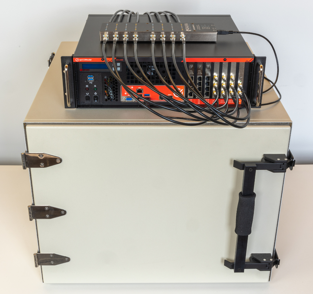
The attenuator can sit directly on top of the NTA3000. Use the eight included coax cables to connect from the antenna connectors on the front of the NTA3000 to the eight “RF IN” connectors on the attenuator. The tests in the CDRouter Wi-Fi Range vs Rate Expansion expect a particular mapping between the individual Wi-Fi cards installed in the NTA3000 and the channels used in the attenuator. Connect the coax cables as shown in the table. Note there will be three unused antenna connectors on the front of the NTA3000. These should each have one of the included plug terminators installed.
| NTA3000 Wi-Fi Connector | Attenuator Connector | |
|---|---|---|
| wifi1-ax24 / wifi2-ax56 (top) | plug terminator (no connection to attenuator) | |
| wifi1-ax24 / wifi2-ax56 (middle) | channel 1 RF IN | |
| wifi1-ax24 / wifi2-ax56 (bottom) | channel 2 RF IN | |
| wifi3-ax24 / wifi4-ax56 (top) | plug terminator (no connection to attenuator) | |
| wifi3-ax24 / wifi4-ax56 (middle) | channel 3 RF IN | |
| wifi3-ax24 / wifi4-ax56 (bottom) | channel 4 RF IN | |
| wifi5-ax24 / wifi6-ax56 (top) | plug terminator (no connection to attenuator) | |
| wifi5-ax24 / wifi6-ax56 (middle) | channel 5 RF IN | |
| wifi5-ax24 / wifi6-ax56 (bottom) | channel 6 RF IN | |
| wifi7-be (top) | channel 7 RF IN | |
| wifi7-be (bottom) | channel 8 RF IN |
Power and Control
The attenuator should use a single USB connection for both power and control. Use the included USB cable to connect the attenuator to any available USB port on the front of the NTA3000. Note that no Ethernet connection is needed.
Running the cdrouter-attenuate command
CDRouter versions 15.3 or newer include a script called cdrouter-attenuate that can be
used to configure and control the attenuator from an NTA3000. To get started,
open a terminal and run the following command as the root user:
/usr/cdrouter/bin/cdrouter-attenuate -help
Here are a few examples of common usage:
Get the status of all channels:
/usr/cdrouter/bin/cdrouter-attenuate -status
Set all channels to 10 dB:
/usr/cdrouter/bin/cdrouter-attenuate -db 10 -all
Set the default startup attenuation of all channels to 0 dB:
/usr/cdrouter/bin/cdrouter-attenuate -defaultset -dblist 0
Antenna Connections
You can connect up to eight of the tri-band antennas you received with your NTA3000 to the eight “RF OUT” connectors on the attenuator. Or if you purchased the Advanced Accessory Pack, you can make use of the magnetic antenna bases.
For RvR (Range vs Rate) or other attenuation-sensitive testing, the antennas must ultimately be located inside an isolation chamber, with the NTA3000 and attenuator physically isolated from the DUT — see Wi-Fi Chamber below.
Wi-Fi Chamber
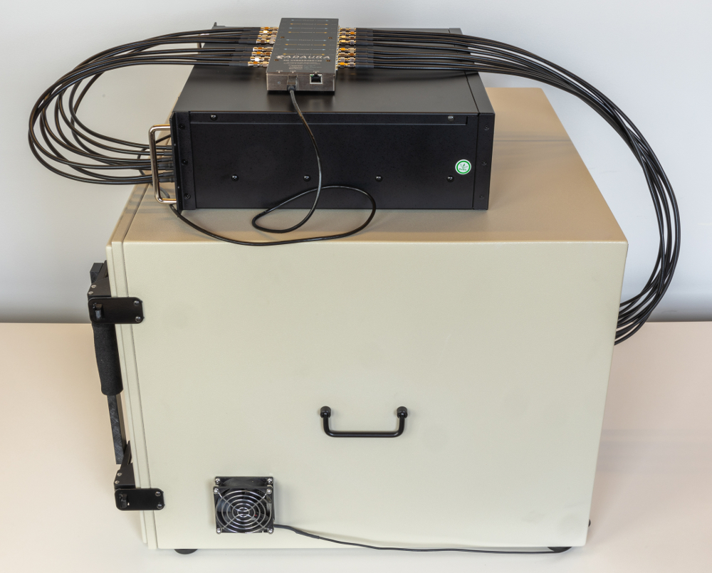
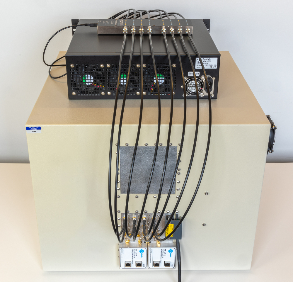
When using a Wi-Fi chamber with the attenuator, the antennas and DUT are located inside the chamber, while the NTA3000 and attenuator remain outside. Additional coax cables connect from the attenuator “RF OUT” connectors to feedthrough panels on the chamber, which route through to the antenna connectors inside. If you need cables for this, contact sales@qacafe.com.
This physical isolation between the attenuator and the DUT is required for accurate RvR testing — without it, RF can leak between the two and flatten the attenuation curve at higher attenuation values. The photos below show a correctly isolated setup using a small dedicated chamber, which is what QA Cafe uses and recommends. The same isolation can also be achieved using feedthrough panels on a large chamber, if available.
RF Connectors
To ensure optimal performance and compatibility with your Wi-Fi setup, always use RP-SMA male and female connectors. Standard SMA connectors may appear similar but are not compatible with the NTA3000 or RAK. When in doubt, look for the reversed center pin — it’s the key to getting the right fit and function.
| Type | Compatible | |
|---|---|---|
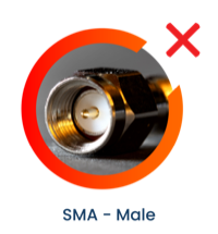 |
SMA Male | No |
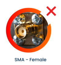 |
SMA Female | No |
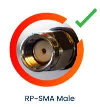 |
RP-SMA Male | Yes |
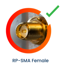 |
RP-SMA Female | Yes |
If you need to connect SMA equipment to an RP-SMA connector, SMA to RP-SMA adapters are available and can be a convenient option for bridging the two connector types.
If you have any questions about connectors or cabling, please contact support@qacafe.com.
